A restriction orifice is a simple, inexpensive device used to limit the flow of fluids. Despite their simplicity they are often used in safety-critical situations, such as limiting the vapour flowrate to within the capacity of a relief valve or controlling the rate of an emergency depressurisation. Accurate sizing of the orifice is therefore critical but is often misunderstood.
Whilst the Bernoulli-derived equations for flow through an orifice are well documented in literature, such as in Crane Flow of Fluids, this information is tailored toward flow orifices that are used for measuring flowrate via differential pressure.
Typically, these operate with a small differential pressure and the flow across the orifice is sub-critical. For a restriction orifice, differential pressure is usually large, and the flow is often critical. Therefore, the typical value of ~0.6 for the coefficient of discharge, C, is only suitable for sub-critical flow and is not suitable when sizing a critical flow restriction orifice.
The primary reference that engineers are directed to for the sizing of critical flow restriction orifices is the Flow Measurement Engineering Handbook by R. W. Miller. This provides equations specifically for a thick, square-edged orifice. The definition of ‘thick’ is where the plate thickness/orifice diameter (t/d) ratio is between 1 and 7. Within this region the flow is choked as the differential pressure is greater than the critical pressure ratio, and the coefficient of discharge is shown to be constant with a value of C of 0.83932.
This is based upon the work of A.J. Ward Smith and is highlighted in the figure below.
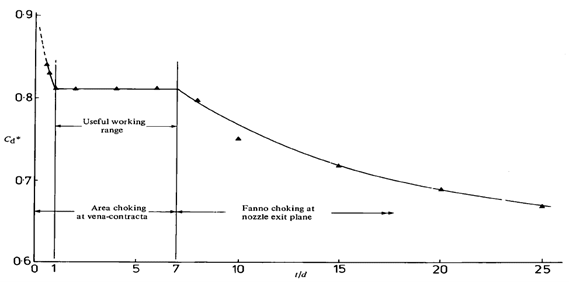
Below a t/d ratio of 1 an interesting phenomenon occurs where the flow does not choke irrespective of the differential pressure across the orifice. This is explained by the vena contracta not being contained within the orifice and exists some distance downstream of the orifice. It is therefore free to increase in size, and so pass more flow, when downstream pressure reduces. This effect is highlighted in the figure above by values of C>0.83932.
In summary, care must be taken when sizing a restriction orifice with consideration of both differential pressure and plate thickness when determining the appropriate coefficient of discharge.
REFERENCES
Crane, Flow of Fluids, Technical Paper No. 410M, 2009.
Flow Measurement Engineering Handbook, R.W. Miller, 3rd Edition, 1996.
Critical Flowmetering: The Characteristics of Cylindrical Nozzles with Sharp Upstream Edges, A.J. Ward-Smith, 1979